My post this morning will focus on the
UV Mapping.
Please note,
these reflections on textures are not a criticism of Mike’s work: when publishing his addons, he did his work for FSX with the tools he had at his disposal and in the state of the art: the work he did was remarkable. Since many things have changed with MSFS, other more powerful tools have appeared and other techniques too, and therefore, in order to be able to use these new potentials, it is necessary to improve certain techniques .
When FS2004 appeared, there were only two software that allowed to build an aircraft:
FSDS and
Gmax. Although these two tools are efficient, they were limited compared to
3DS Max (prohibitive cost), especially in the field of
3D preparation for creating textures, which is called
UV mapping, this term covers the operations that allow a 3D surface to be projected onto a plane: the texture.
In 2004, to paint a fuselage, the author took two side views (right and left), and these two views made the job. Nevertheless, the top and bottom of the fuselage were poorly treated because on the texture these areas were represented by a very few pixels, so in the simulator, when the aircraft was seen from above, distorted, stretched paintings were observed that misrepresented these parts (
a screenshot doesn’t seem necessary to me because almost everyone has already seen this)
In 3DS Max, the UV mapping tools were better processed and we could virtually "cut" the fuselage into 4 parts: top, bottom, right, and left, which allowed us to paint each part of the fuselage homogeneously.
PS: on Gmax, this was also possible ... but much more difficult on some aircraft's parts.
At that time, the textures used were
diffuse, specular, and
bump. The rendering of light reflection in simulators has since been greatly improved thanks to
PBR textures management, which uses others textures : albedo (~diffuse), comp (ao, roughness, metallic), normal (~bump), and emissive if necessary on some parts.
Without going into details, this way of doing things allows a much more realistic rendering. That said, the UV mapping of visualized objects still needs to be appropriate and much more careful to take advantage of this way of representing light and reflections on objects.
Since 2010-2015,
Blender has started to be actively used (on FSX, P3D and X-Plane) and its UV Mapping functions have nothing to envy to those of 3DS Max,
but you still need to use these particular functions.
These functions make it easy to select edges of the 3D object and to particularize them by creating "
seams", so that when the developer projects these objects on a plane, the object will unfold with minimal distortion on the horizontal plane, a bit like when you take a tube and cut it lengthwise so that you can spread it: the longitudinal cut is the seam I was talking about.
In this way, we can create a precise texture for each part of the tube (front - back) and not a symmetrical texture because most of the time in FS2004 we only used one projection and the front vertices were superimposed on those behind.
This way of doing things was faster, but if you want to use the full potential of PBR textures, you have to review how to manage UV and generally redo them when you do an airplane conversion.
Many developers who publish on FS.TO tend not to bother with these considerations, and by using the old mapping do some work that is not at the required level to use all the potential of PBR textures.
All this explains why I have a rather hard opinion about some creations: I recognize that

.
All these preambles to explain to you that transforming an aircraft that used the old representation of textures into a PBR environment still requires significant and essential work.
In the DC-4, I took as an example pilot seats, which seem to be simple objects, and yet here is the UV mapping from the P3D models. Either the parts surrounded by red have been placed on other parts and they are not unfolded but simply projected: the example of the tube with the vertexes that overlap ... moreover, the steel tubes that make up the reinforcement (surrounded by blue) have precisely this problem !
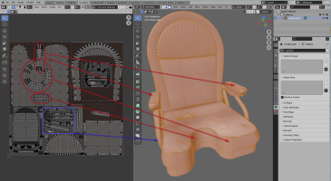
Therefore, to comply with my methods of making, a certain number of objects will have to be reviewed and their UV mappings modified, which implies that the old textures will no longer be usable as such.
For the interior, it’s not too penalizing except for certain panels or objects that are in the user’s field of view and that some repainters will want to modify. Moreover, there is no point in turning ALL objects into PBRs, only those that are large in size, that are very often visible to the user, and that can fully benefit from this additional processing.
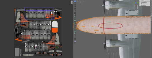
What will be more delicate is for the exterior textures, especially the fuselage, where I would have liked to use the existing ones to properly insulate the bottom and top
(blue square) so that they are better represented. On the screen below (
red circle), Mike had put a plane on the top of the fuselage to be able to correctly represent the dirt from the heating outlet (
I suppose)
 So as not to break the exterior paint kit
 while trying to improve things, I plan to try :
- to cut out the top and bottom of the fuselage and
- create an extra texture set (4096 x 1024) to represent these cut parts of the aircraft.
So that the paintkit remains usable, nevertheless, we must not forget to adapt the 3 new textures for the fuselages.
For wings, UV mapping is generally good because they have only one top and one bottom, which is well processed regardless of the tools used.