Thank you Maty; yes, I have that cut-a-way and refer to it often.
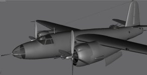
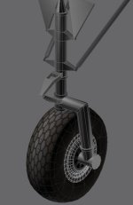
Now with the annual RTWRace completed, I am easing back into the Marauder. I think before I address the issues/observations above, I will start putting together the components of the flight model and get that ready for the gear build process.
Now with the annual RTWRace completed, I am easing back into the Marauder. I think before I address the issues/observations above, I will start putting together the components of the flight model and get that ready for the gear build process.
 .
.
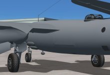
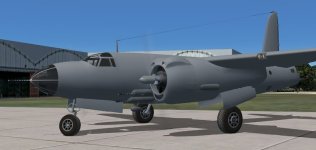
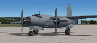
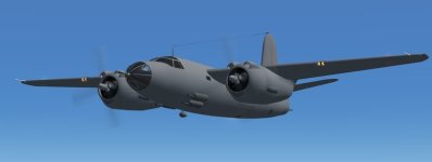
") She does seem to be shaping up rather well.
She does seem to be shaping up rather well.